Reflection
To start the day Kris explained a few things to us:
- We can understand the orientation of components by identifying the circle or rounded edge on the corner with pin number 1.
- We can add a little solder to the braid to make everything easier.
The goal for today was to finish soldering the board, debugging the board and actuating the servo motor.
Soldering
I started the day with soldering my 4th board. This time I actually did the solder very successfully and got all components soldered on the board as you can see below:
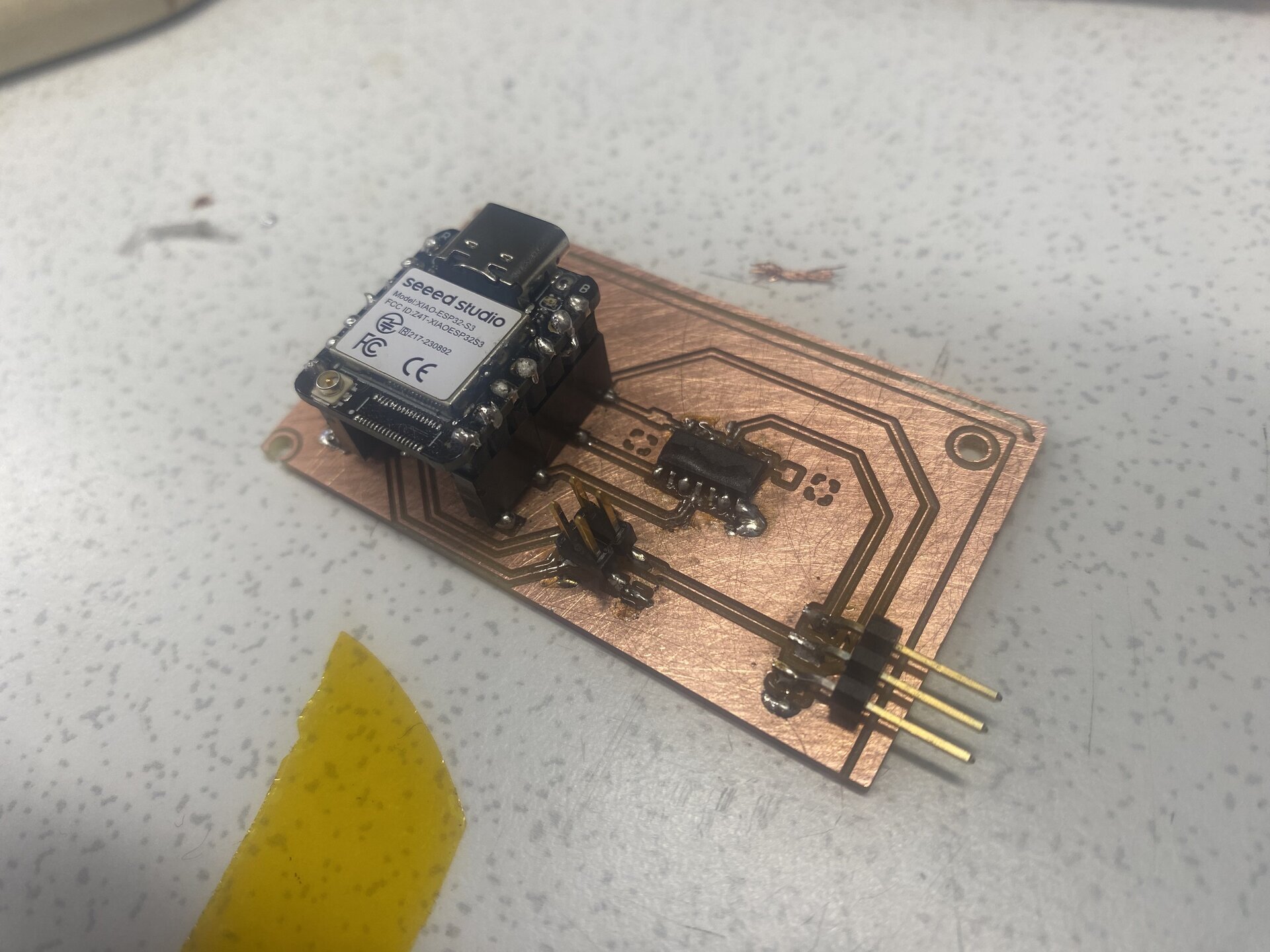
But after I finished it I realized that I soldered the level shifter exactly 180 degrees flipped. I decided on the orientation in the morning based on the text on the level shifter but actually the text’s orientation can vary based on the factory produced. But the real indicator of orientation is the little circle engraved in the corner where pin number 1 is located.
So after I realized this I decided to desolder the component using the hot air gun. I had help from Kris during this process as you can see in the video below:
After this process some plates of copper lifted but they were plates of pins we didn’t use so it wasn’t a problem. But after soldering it with the correct orientation I realized that the SMD pins for the ESP32 were doing a short circuit. While trying to fix that short circuit I accidentally lifted a copper trace that was vital for my board. So this was my 4th failed board .)
Now after all of my failed boards I used the experiences I gained from those to solder a fully working board as you can see in the hero shot below:
I tested all the connections using a multimetre and actually fixed two separate short circuits that I thought weren’t a problem initially. There was an island that was independent from the ground and the solder for the 5V accidentally touched that island and I thought it would not be a problem but actually there was a capacitor that connected the island and common ground. So when I gave power to my board the capacitor made it so the common ground connected to the island and in turn connected to the 5V which made a short circuit.
So I basically removed the solders that connected the 5V and the island.
Also I thought that the no connect pins of the ESP connecting to the common ground wouldn’t be a problem but that also produced a short circuit causing ESP to malfunction so I also desoldered there too.
Actuating the Servo
After fixing these I could tell the board was working by the indicator lights on the ESP as you can see below: 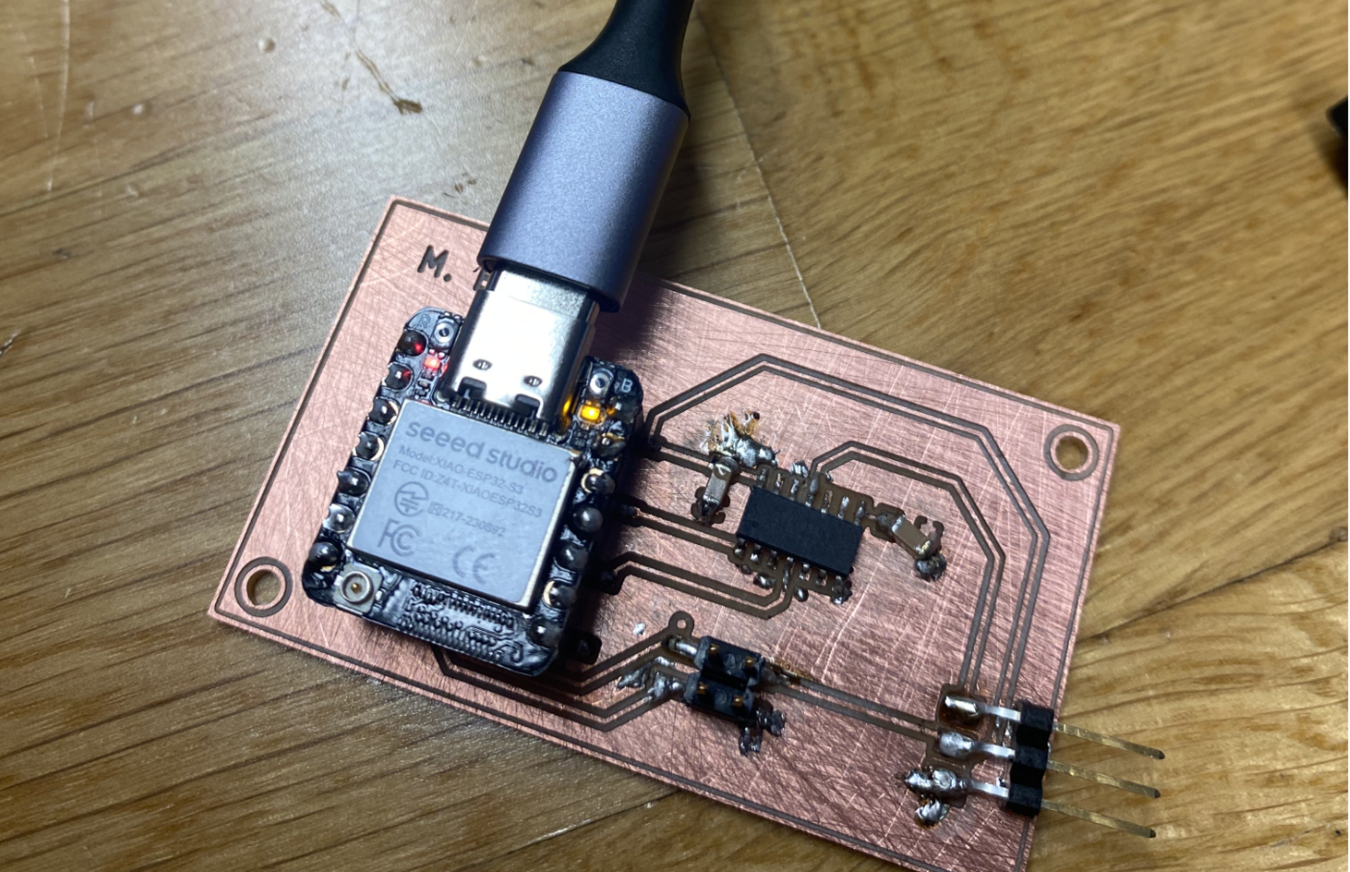
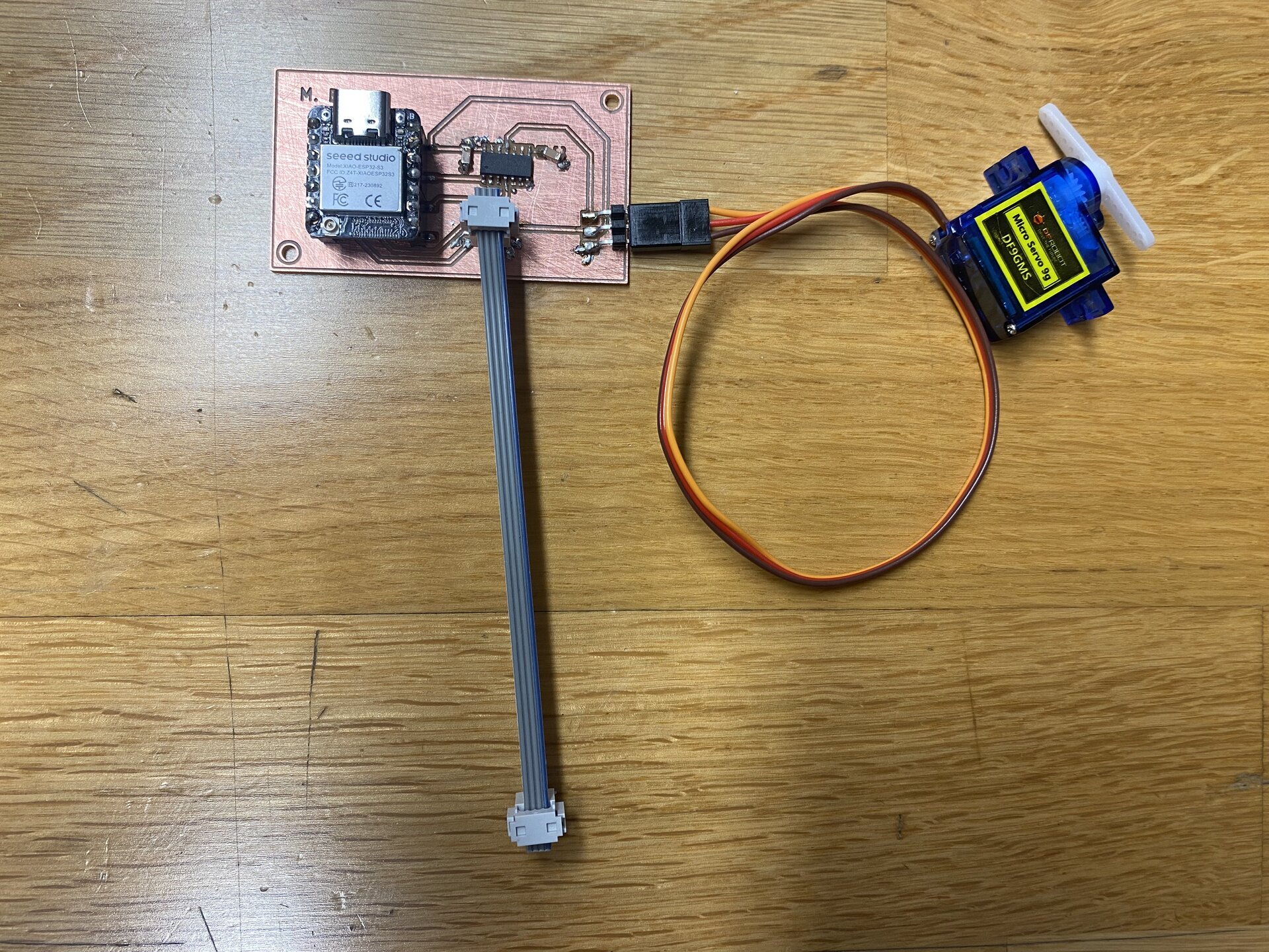
Below is a photo of all the components connected to the board:
Then I moved on to programming. Below is the code I wrote to actuate the continuous servo motor:
#include <ESP32Servo.h>

Servo s;
void setup() {
s.setPeriodHertz(50);
s.attach(8, 500, 2500);
}

void loop() {
s.writeMicroseconds(2000);
delay(3000);
s.writeMicroseconds(1500);
while(true);
}
And finally here is the working actuated servo demo video:
This day was overall very successful as I soldered and programmed a working board that can actuate a servo motor and connect to other boards via i2c. Despite lots of failed boards and solders I learned so much about soldering today.
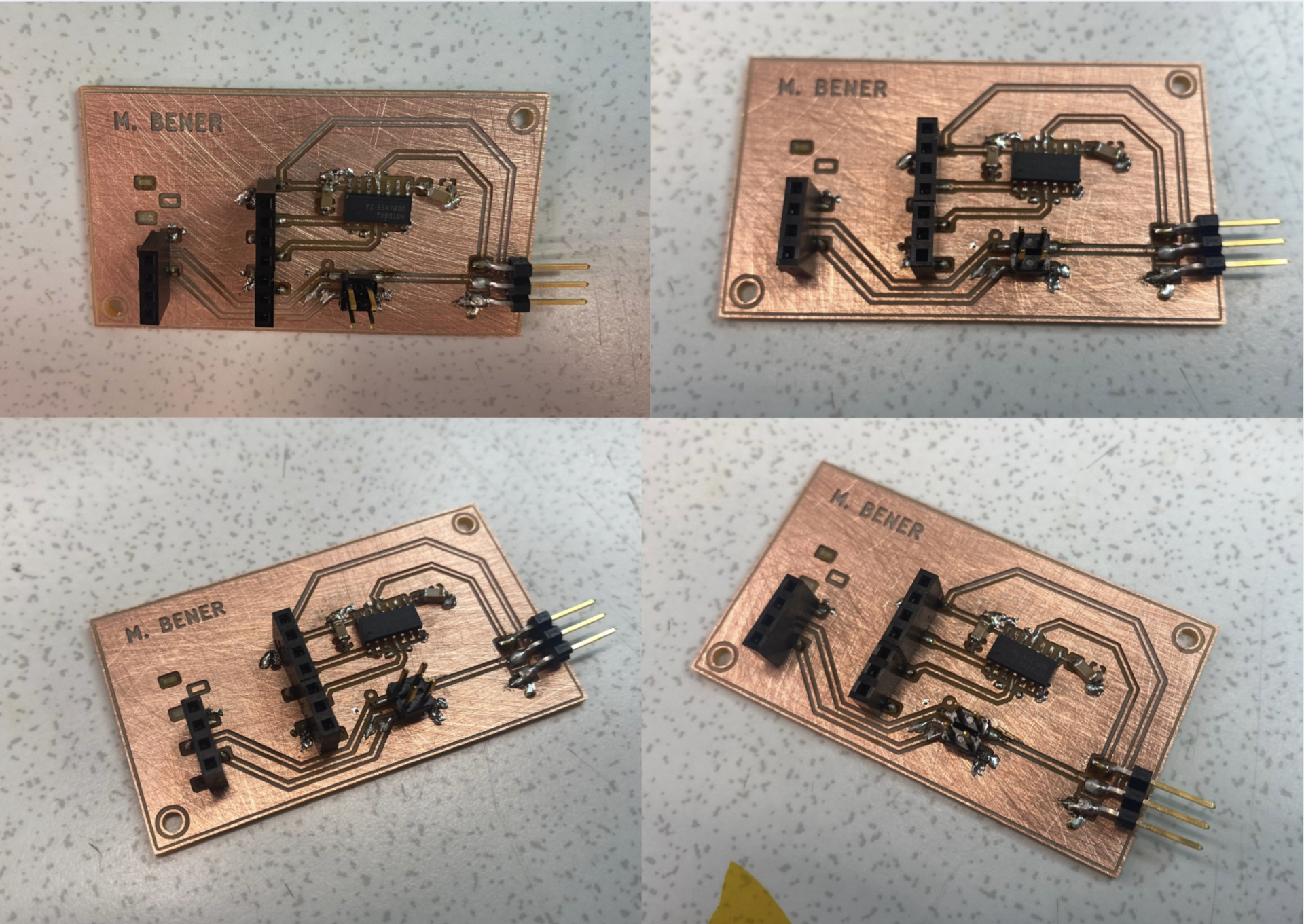
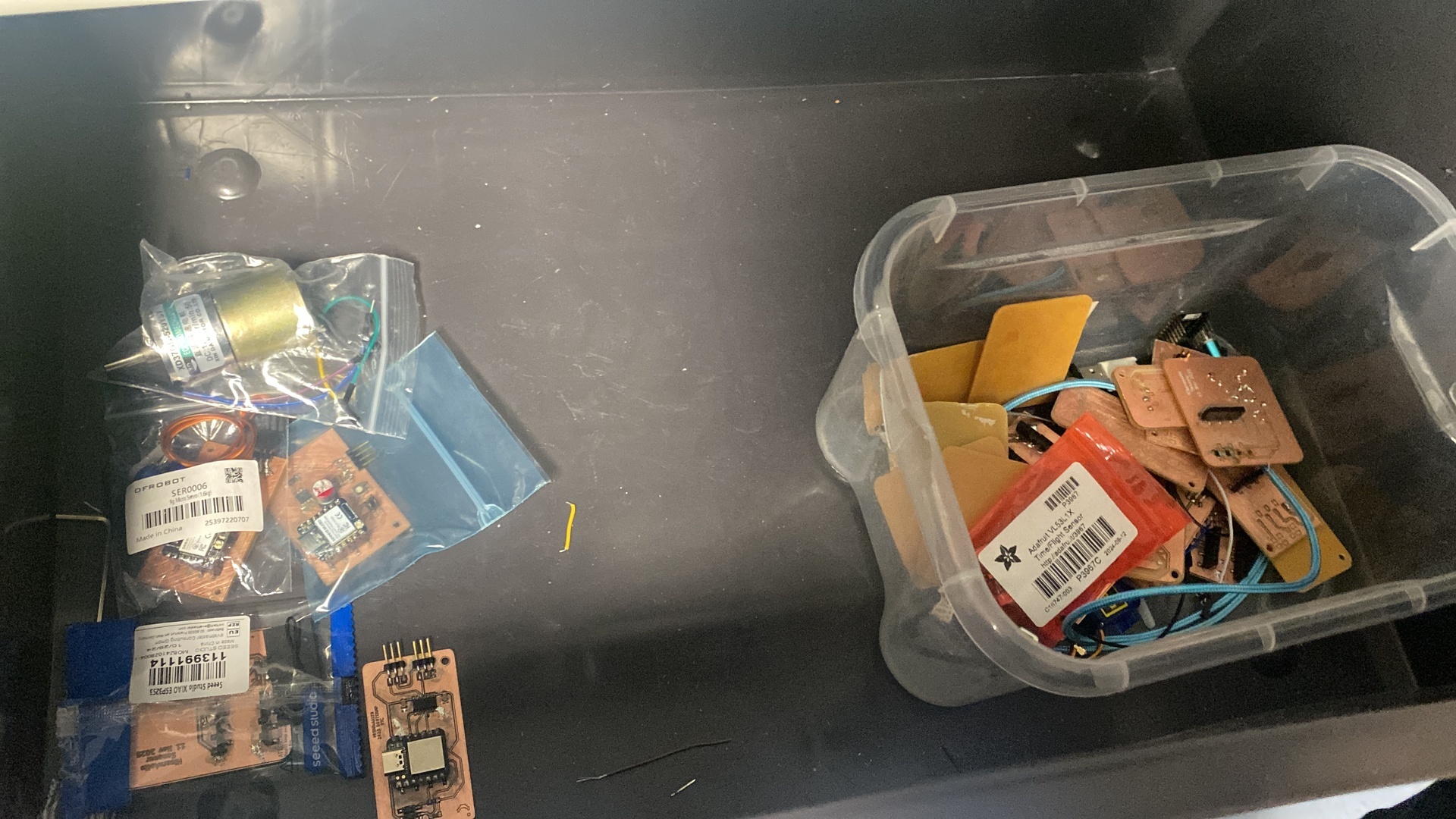
Before going out as a group we organized all our failed and finished boards into a box as you can see below:
Tomorrow we plan to communicate the boards and actuate motors based on data coming from input devices.