Introduction
In our first day in Aalto University we met with Mr. Kris and Mr. Solomon and introduced ourselves. Then we continued with a tour of the Fablab. Then we started discussing about possible project ideas we could complete in this five day bootcamp. As a three person group: Me (Mehmet), Kerem and Can we thought of an idea.
Project Idea: Conveyor Belt Sorting System
Mechanism:
Our project uses a conveyor belt, DC motors, and a color sensor.
Objects move along the conveyor belt toward a forking path equipped with the color sensor. When an object reaches the sensor, the color is detected, and the microcontroller sends a signal to control a servo-driven gate. Based on the detected color, the gate directs the object to either the left or right pocket. Multiple levels of sorting can be achieved by chaining more gates.
Purpose:
To automatically sort objects based on their color, improving efficiency, accuracy, and speed in industrial or packaging processes.
This minimizes human error and reduces the time required for manual sorting.
Example:
Factories: Sorting packaged products by color or label type.
Recycling Plants: Separating colored plastic bottles or materials.
Food Industry: Categorizing fruits or candies based on color.
Educational Demonstrations: Teaching automation, sensors, and embedded system concepts.
Sketch:

Work Division We divided the project into three modules, each designed and fabricated by one person:
- Servo Module: Controls the gate and pushes objects into the boxes (Mehmet)
- DC Motor Module (Conveyor): Drives the conveyor belt (Kerem)
- Photo Sensor Module: Detects object color and communicates via I2C (Can)
All three modules will be connected through I2C communication between the microcontrollers.
Electronic Design: KiCad
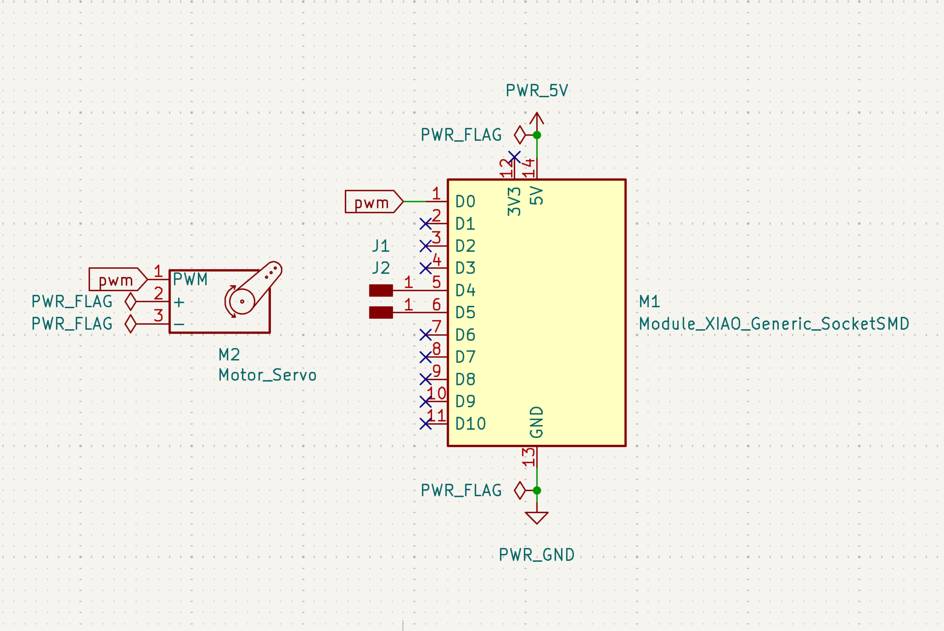
Now my task was to design a board that controls a servo motor with a microcontroller. First I imported the symbol “Module_XIAO_Generic_SocketSMD” in place of my ESP32 microcontroller. Then I made my first mistake of importing a symbol for my servo motor when my servo motor actually wasn’t supposed to be on my board. The servo motor will be connected using jumper cables to the custom board. I created two separate pin headers for the i2c connections on D4 and D5 (SDA and SCL). Then I connected a GPIO pin, GND and 5V to the servo using flags. My schematic of this mistaken design is below:
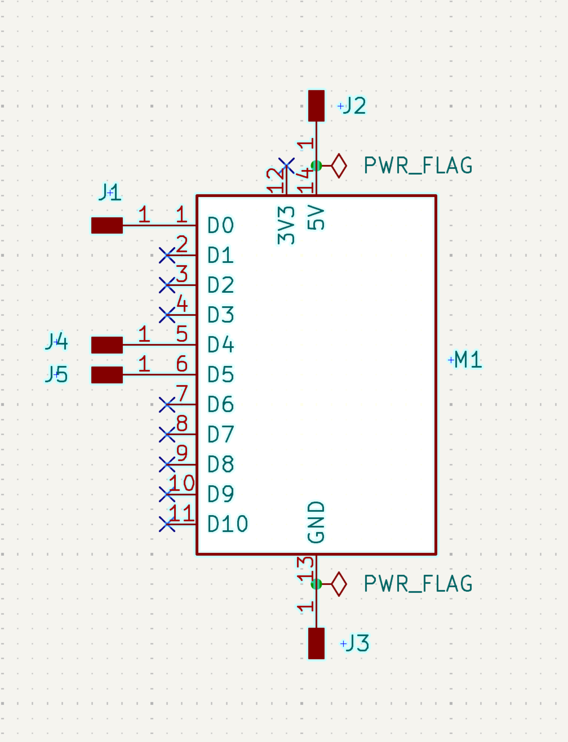
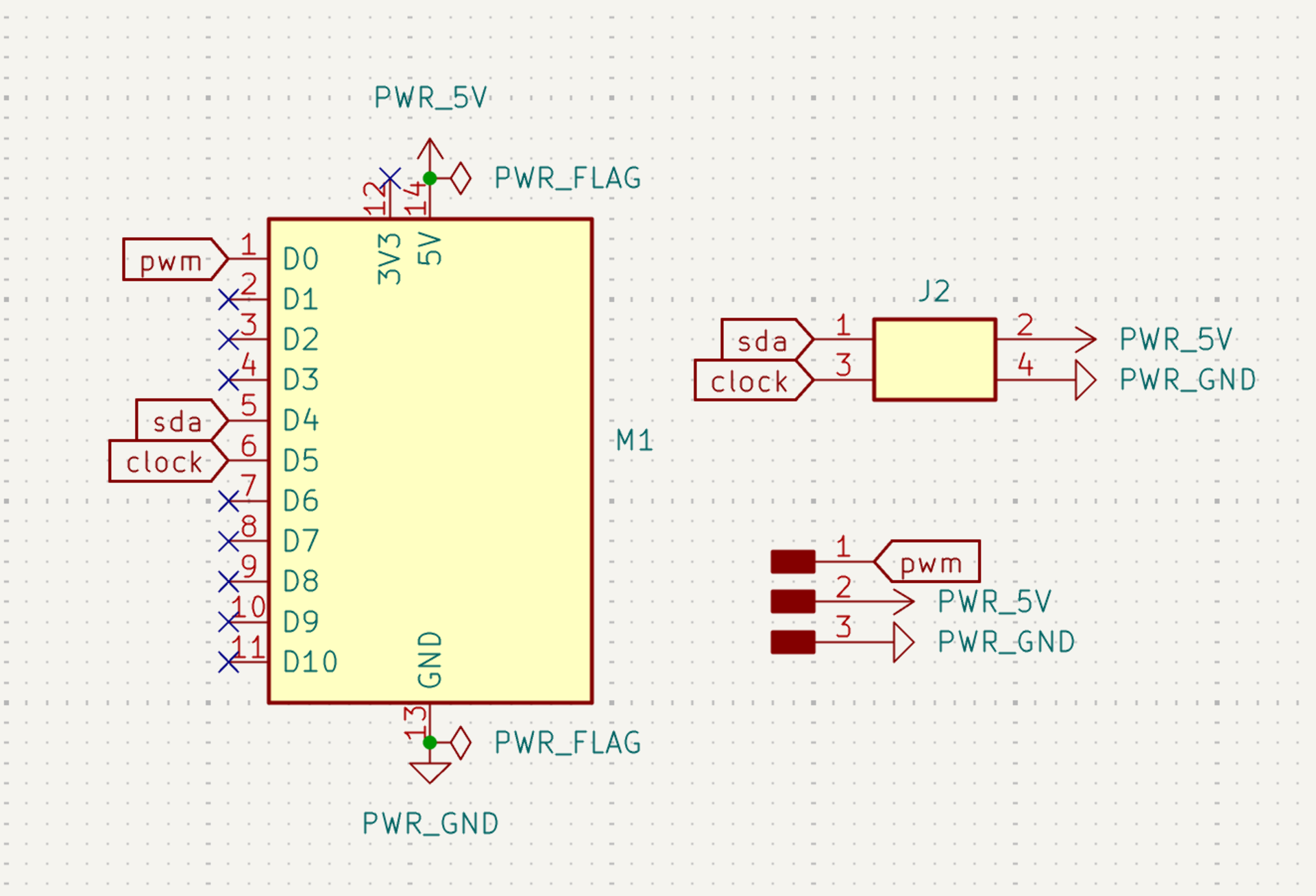
After I realized my mistake I removed the servo symbol and simply created separate pin headers for the GND, 5V and GPIO pin. But this approach was wrong too because the pins were seperate and using 3x1 pin headers for servo and 4x1 pin headers for the microcontroller would be better. But here is the mistaken v2 schematic below:
!
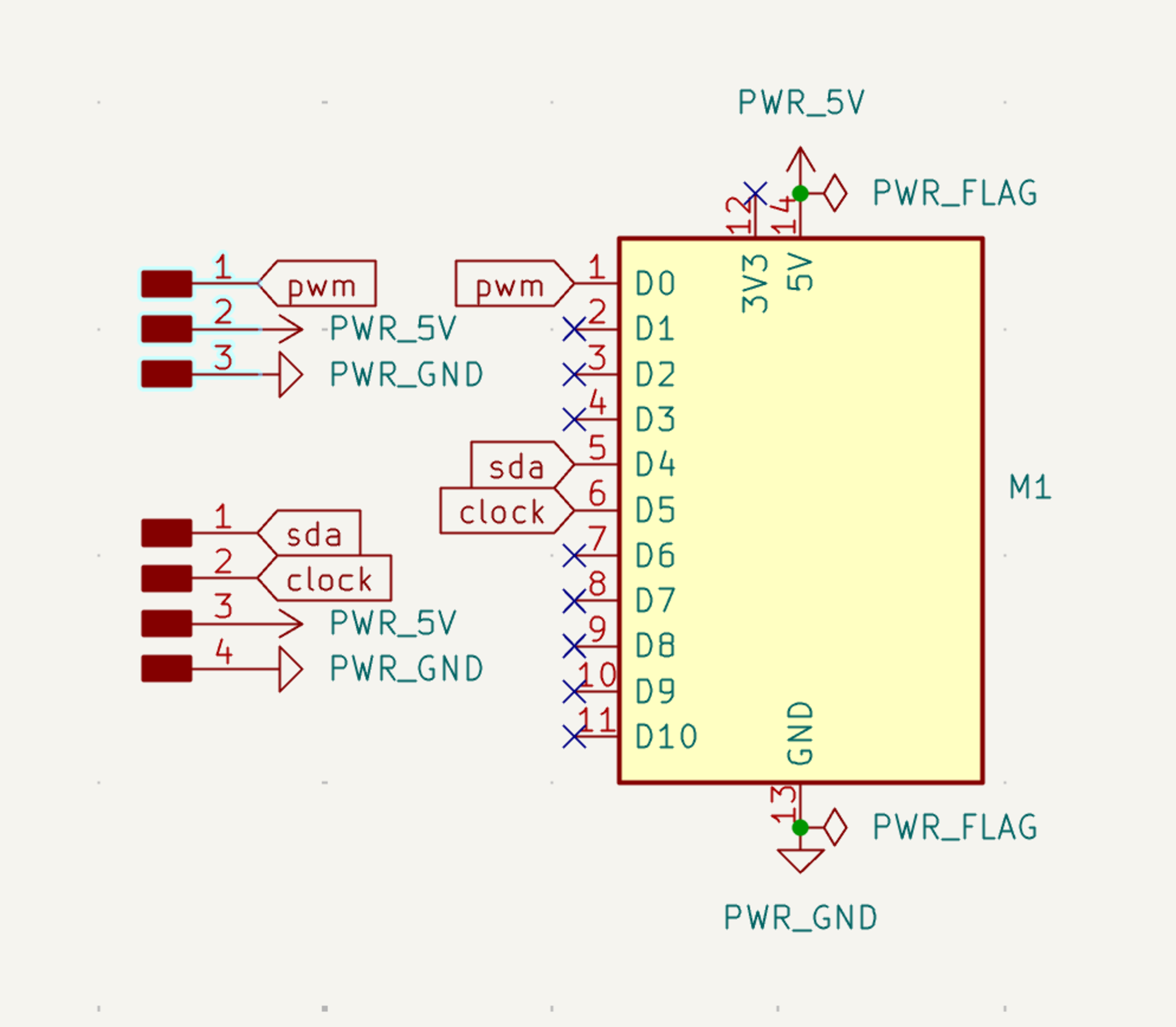
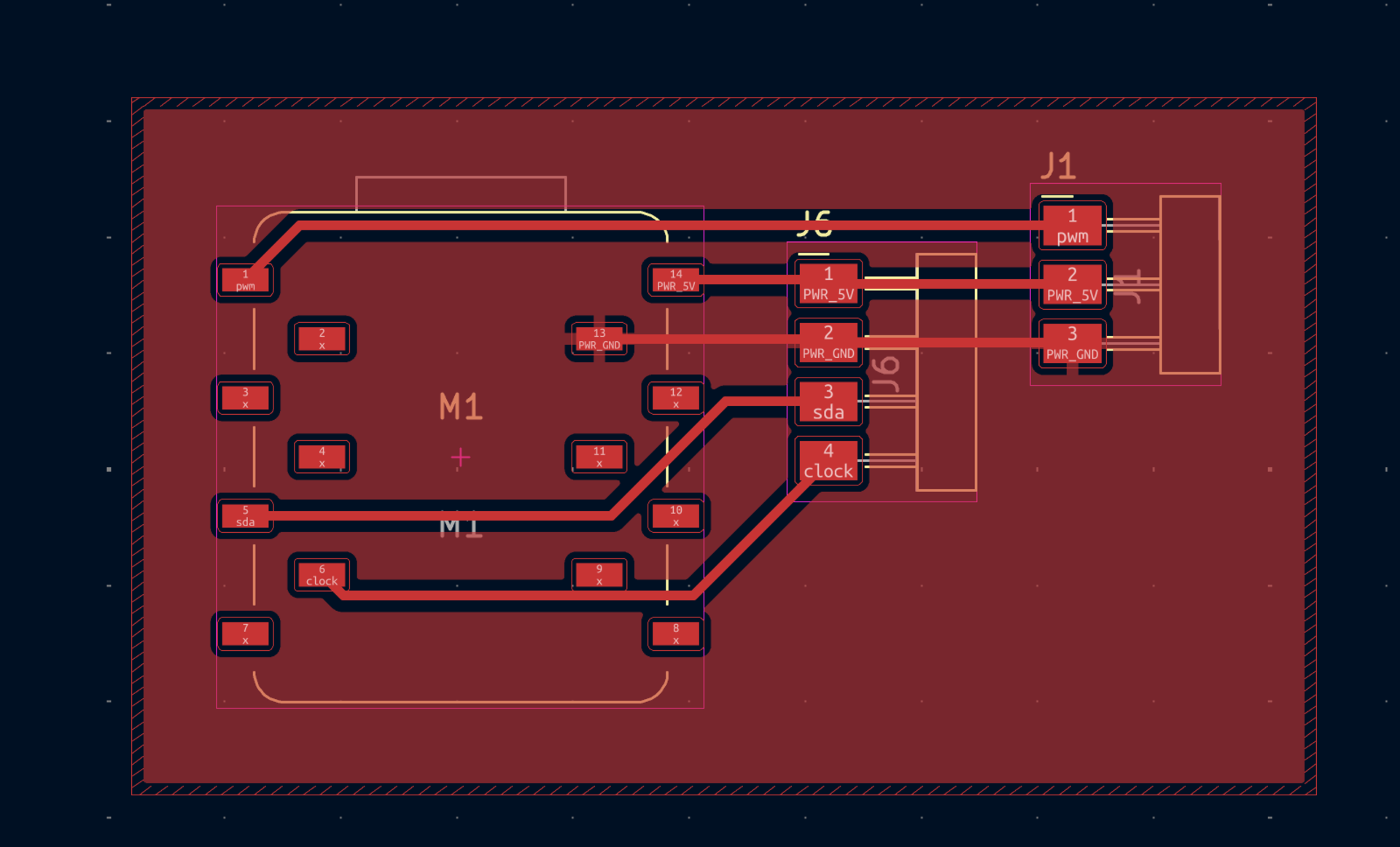
And now by combining the pin headers I finished my schematic that got zero errors and zero warnings on the ERC. You can see the schematic below:
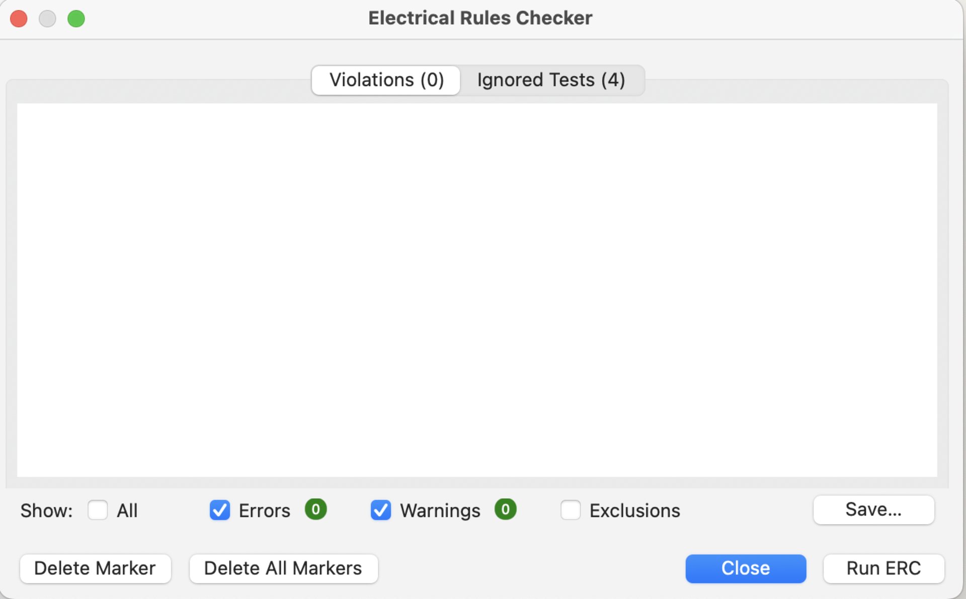
You can also see the zero error ERC below:
The next step was to convert this schematic to a PCB design. I switched to the PCB page and transformed my schematic. Then I changed the track width to 0.4 mm from 0.2 mm for ease of soldering later on. The tracks I drew were optimized by me to make my soldering easier later on. Final PCB design screenshot:
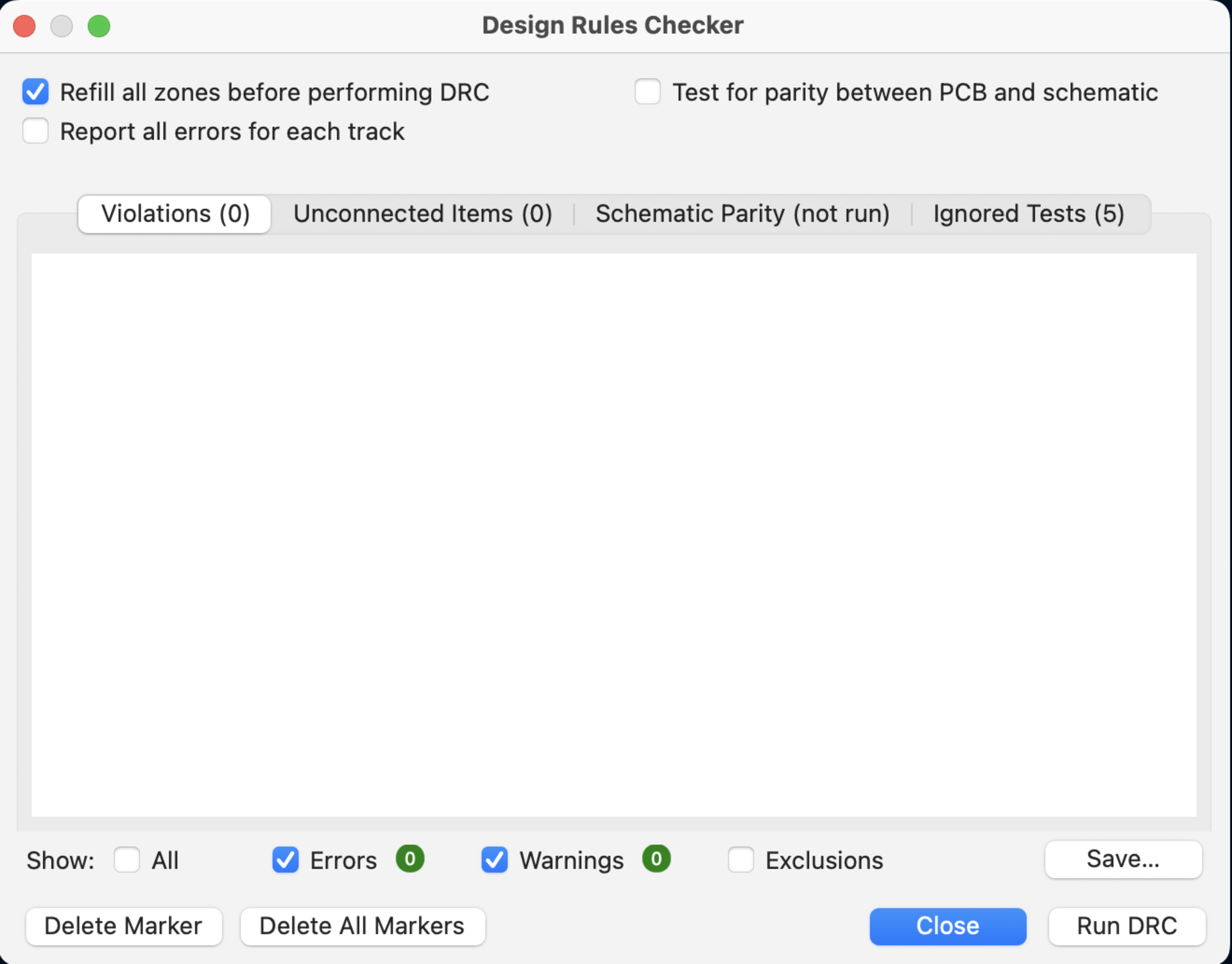
I also got zero errors and zero warnings on the DRC:
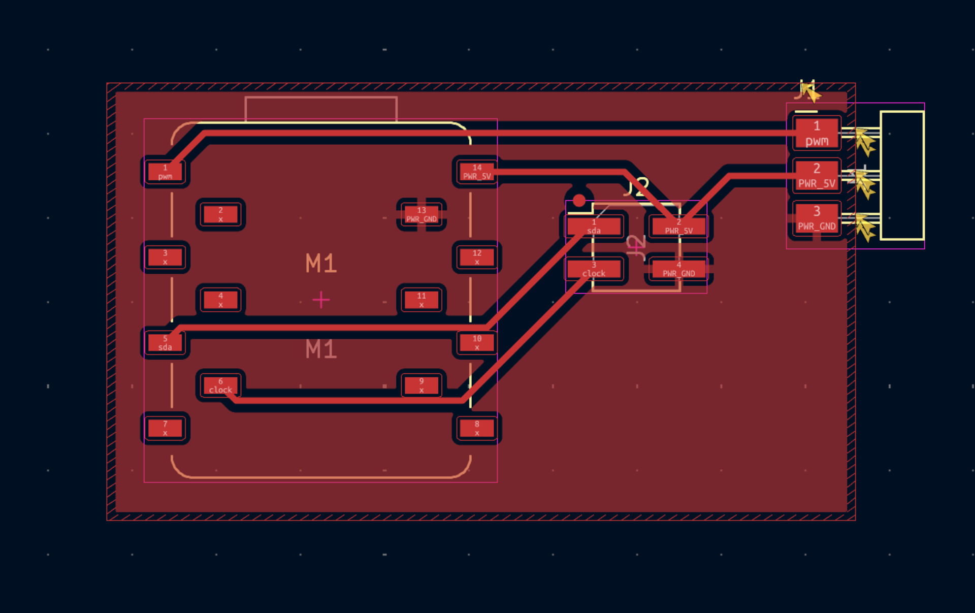
Then I showed my design to Kris to get some feedback. He told me that the pin headers that we have available in the lab were vertical pin headers. I was using horizontal headers. So I changed that. Updated schematic and pcb design:
This is the how I created the final board design of my servo motor and microcontroller using KiCad.
3D Design
Next, I will design the servo mounting system and gate mechanism in Fusion 360. This part will include:
- A servo holder connected to the main chasis
- A gate connected to the servo motor
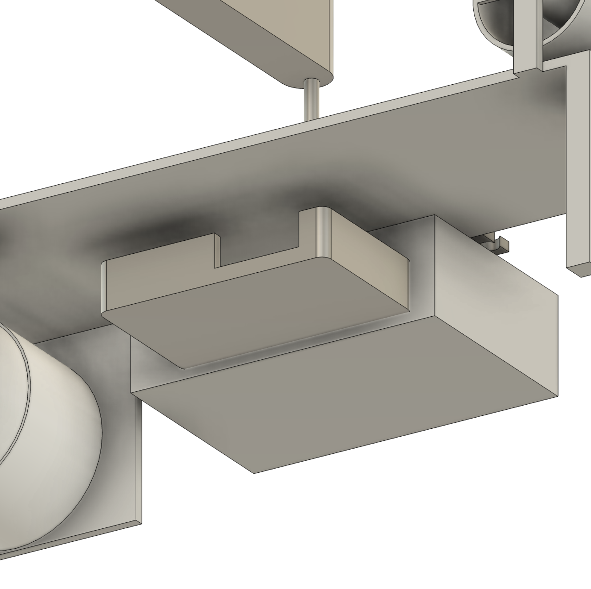
I will also design an enclosure for my pcb module that’s integrated into the final product.
Design of the enclosure can be seen below:
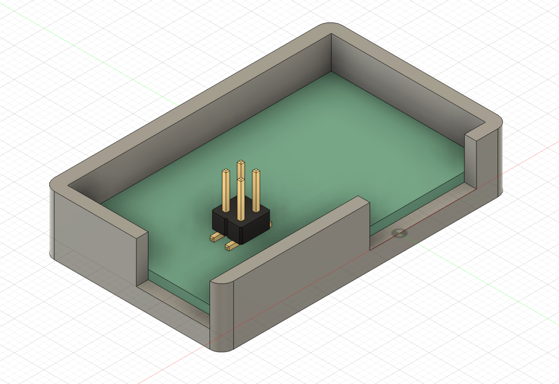
The two gaps in the wall are for the horizontal pin headings and the usb of the microcontroller.
Design of the servo holder and gate integrated into the system can be seen below:
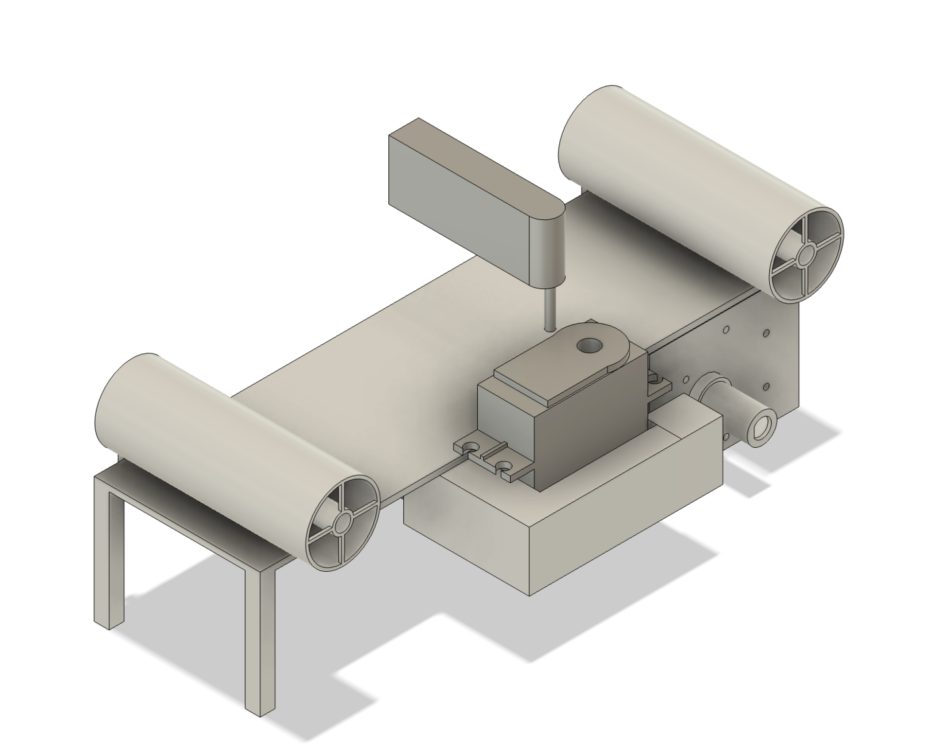
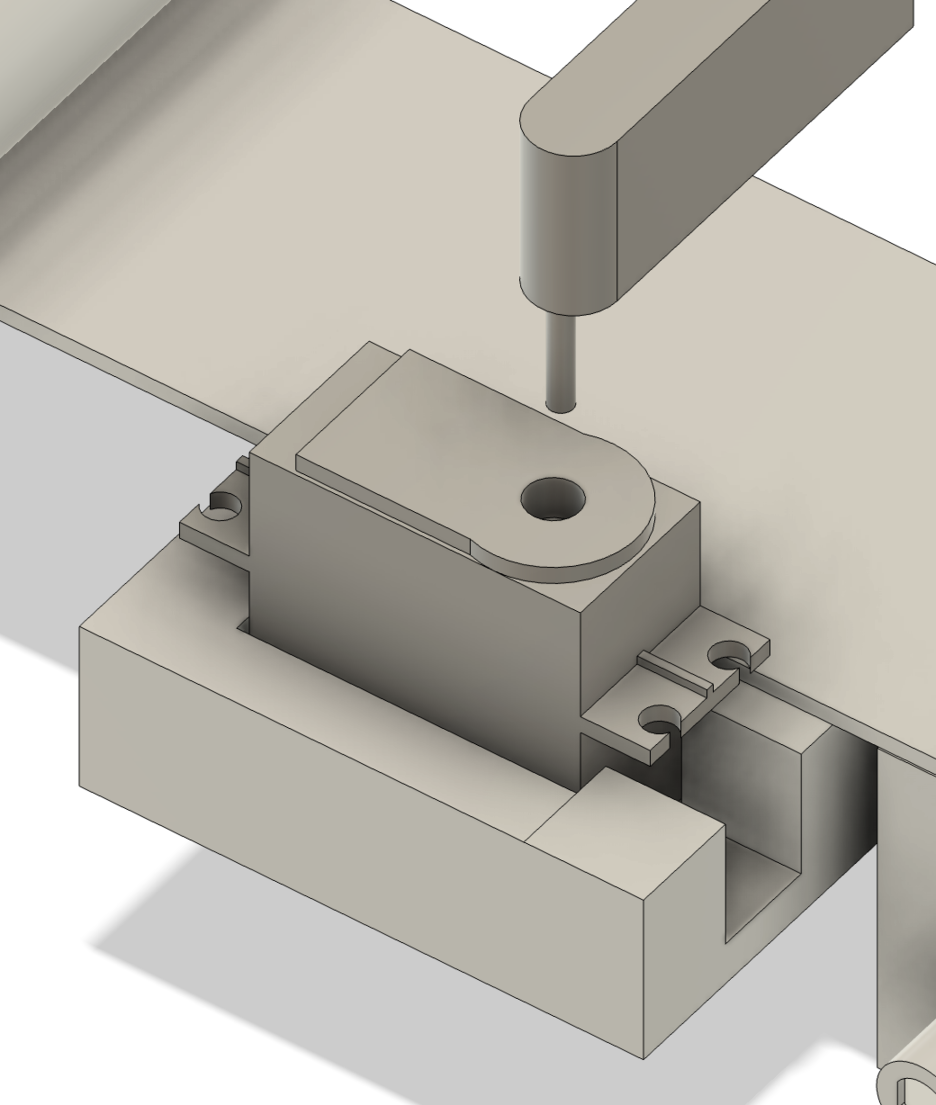
 Basically I added the gate and servo board module part to the design made by my group mate Kerem. I added my PCB enclosure, a servo holder and a gate that can be connected to the servo using M2 screws.
Reflection
Today was an exciting start. I learned how to go from concept brainstorming to actual board design in a single day. I made multiple schematic design errors and corrected them, gaining a better understanding of how to structure modular boards.
This day also helped me get familiar with Aalto’s fabrication environment, improved my KiCad design workflow, helped me understand documentation best practices and design a CAD model that integrates a PCB.
Tomorrow, I plan to mill and solder my board.